Hiya all,
Hope you're all keeping well.
Back to some more antics building stuff.
Some of you may recall I went mad, (yeah, I know, already 'mad'

), and bought myself a late 1970's 2m radio just because I liked the look of it.
https://charlietangodxgroup.forumotion.com/t3042-radio-headaches-and-tales-of-an-old-yaesu-ft-227rShe was all working, (how lucky was that?!), but needed dragging into current times as the old 1750KHz burst tone is a bit outdated and no longer able to access repeaters. Enter modern day CTCSS, (Continuous Tone Coded Squelch System).
https://en.wikipedia.org/wiki/Continuous_Tone-Coded_Squelch_System
A quick scout around the web and there are plenty of sellers of these little devices of various design as well as prices to retrofit to older radios.
I only wanted a 77Hz tone to access my local repeater GB3PI so rather than simply buy one.....I thought I'd build one!

You could do the same as other designs, choose a microcontroller, hookup a programmer, learn to program a microcontroller, find out you're useless at it and search the internet for help only to be left disappointed.....
.....I thought I'd go old school and build an analogue design.
The original Yaesu unit for this radio utilised a Tone encoder/decoder 'chip' the old NE567, another ubiquitous chip designed by Hans Camenzind famous for his LM555 timer design.
https://en.wikipedia.org/wiki/Hans_Camenzind
This integrated circuit only produces a square and triangle wave output so needs a low pass filter to 'shape' the output to a sine wave. This being important so that there are no harmonics on your sub-audiable tone signal. (You'll get annoying tones or droning sounds on your transmitted audio otherwise - some designs on the web don't filter!! Be warned.)
A simple LPF or Low Pass Filter will suffice, so I chose a 'Butterworth' design being familiar with it.
I chose the equally old and in/famous LM741 despite having some modern day op-amps just to keep that old school vibe going.

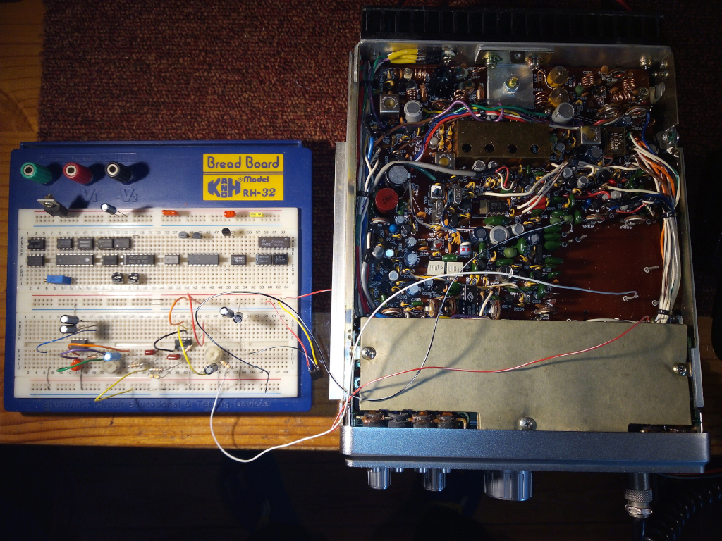
Feverish with excitement I set about collecting the parts I needed and dug out my old breadboard.....

Doesn't look as impressive as it seems but I discovered much to my annoyance that I have not aged gracefully!
My once dextrous hands are reduced to being as 'nimble' as bear-paws! My eyesight isn't doing much better either and I had to dig out my +3 dioptre reading glasses just to read the part values!!
I used my old faithful 1971 all valve Telequipment oscilloscope to check I got a sine wave. The 'jitter' on this old thing meant I wasn't able to get an accurate frequency measurement so resorted to clever use of transmitting through a dummy load on a simplex channel whilst listening on a Baofeng set to 77Hz CTCSS. Twiddled the frequency pot to the LM567 until the squelch broke open on the Baofeng and jobs-a-good'un.

Tested in on the GB3PI repeater, lovely chat with a helpful Ham who gave me an audio report and this breadboarded monstrosity proved it does indeed work.
Time to make it into a 'proper' board so that I can squeeze it into the radio.....
(The breadboard won't fit and I'd like to use it again for something else.

)
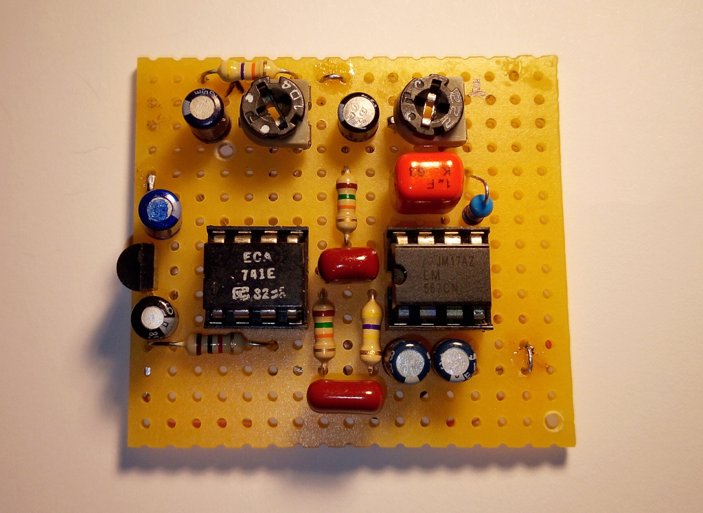
This was where my ageing hands and eyesight became an issue again. A board like this would've taken me mere moments to build as a younger man but took me the best part of the day! After much swearing, mistakes made, dropping parts never to be found again I finally got there.....

None too shabby for an old blind git!
It's not exactly tiny but small enough to squeeze into the FT-227 where the original encoder would have sat.
BTW, this is not 'veroboard', that copper tracked stuff that will have you hunting around for ages for little slivers of solder shorting between tracks! Nope, this is good old plain perforated board, holes and nothing else. Means you can stick the components exactly where you want or need them and wire them together appropriately underneath point to point. (Great construction method if you later wish to produce a PCB - rather than relying on software to do it for you.

)
Now is this old fashioned tech going to be good enough?
Will it wander around the 77Hz meaning you can't reliably open a repeater?
The capacitor I used on the 567 is an MKT or Polyethylene terephthalate film capacitor which is very stable with tight tolerances.
The resistor chosen was a metal film 1% type again for the tolerance and stability.
So how good is it?
Well after subjecting the circuit board to a trip in the deep-freeze compartment of the home refrigerator, (shhh...don't tell the wife!), getting it down to about -10'C it sat firmly at 77Hz. Lovely. So I also subjected it to the heat of a hair dryer, (again...don't tell the wife!!), getting it to a heady 50'C and once again it sat at a steady 77Hz.
My radio room doesn't get to either of those temperature extremes, (thank God!), so it should all be more than OK.
(I was actually impressed it stayed that stable....I'm not even that stable!

)
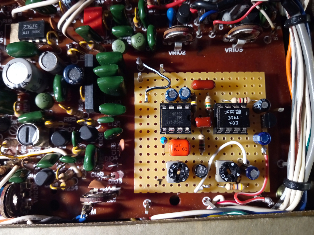
So onto wiring it into the old radio....

Loads of room!
...and yes, I did burn the tip of one finger soldering those wires into there. Only takes the slightest touch of a 400'C iron to make you sound like a wild cat! Cor did I spit!
Anyway, all done and best of all.......I didn't half have fun building it!

The cost? Mere pennies as I had most of the parts laying around in my old component drawers.
The reward? I get to use this old girl in earnest chatting to a couple of my friends calling them on the repeater and even jumping to one of the old simplex channels to chat direct. I may even get to chat to people new on the old GB3PI repeater.
Old radio, old tech from old components, the UK's oldest repeater, chatting to old friends.......
.....being used by an old git operator.
Couldn't ask for more.
Anyway, more of my 'waffle'. I enjoyed writing this up and I hope some of you enjoy reading it.
Take care and all the best,
Victor
26CT3228
M7VIC


